The geology and paleontology of the Caldecott Tunnel's Fourth Bore
II. The geology … and dealing with it
From previous experience, Caltrans knew that the Fourth Bore would be cutting through rocks that are fractured, unstable, and potentially dangerous; during construction of the Broadway Low Level Tunnels (Bores 1 and 2) in the 1930s, four workers were killed and several others injured in two cave-ins. And not helping matters any, the tunnel was going to be below the water table (scroll down to see the East Bay Hills cross-section below); with water finding its way into the cracks and discontinuities in the rocks, an already dangerous tunneling environment is made even more so. Furthermore, there was the possibility of encountering pockets of methane gas, so workers could not bring anything that might make a spark into the tunnel; this meant no internal combustion engines, cell phones, or cameras.
Faults are at fault
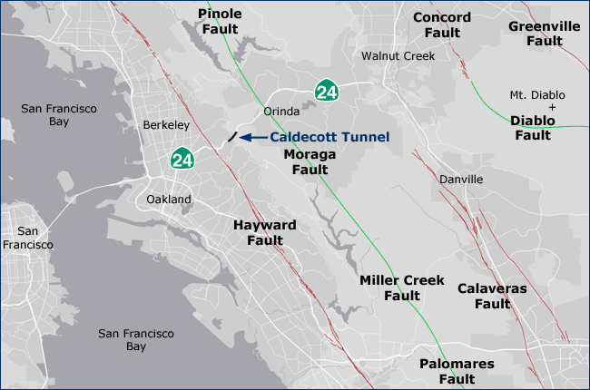
What has made the East Bay Hills so unstable? It's all that faulting and folding caused by the San Andreas Fault System. The Bay Area is riddled with several active faults, both major and minor, strike-slip and thrust. A strike-slip fault is generally a vertical fault along which the two sides move horizontally; a thrust fault is one in which a block is thrust up over another at a low angle. In the East Bay, the two major strike-slip faults are: (1) the Calaveras Fault — it diverges from the San Andreas Fault at Hollister and trends northwest, ending at Danville; and (2) the Hayward Fault — it diverges from the Calaveras Fault east of San Jose and runs northwest along the western base of the East Bay Hills, through UC Berkeley's Clark Kerr Campus and Memorial Stadium, and continuing to San Pablo Bay. Two major thrust faults are: (1) the Pinole-Moraga-Miller Creek-Palomares Fault complex — originates at the Calaveras Fault in the vicinity of Sunol Regional Park and trends northwest, running east of Upper San Leandro Reservoir, between San Pablo and Briones Reservoirs, and on up to San Pablo Bay; and (2) the Diablo Fault — a "connector" between the Concord and Greenville Faults (both are strike-slip faults) that circles the west and south sides of Mt. Diablo. The movement on this active thrust fault is responsible for the mountain's continuing rise.

![]()
Top: Graphical representations of strike-slip and thrust faults. Images from the U.S. Geological Survey Visual Glossary. Bottom: The major faults of the East Bay. Strike-slip faults are in red; thrust faults are in green.
Most East Bay residents are familiar with the Hayward Fault since it gets a lot of press. And rightly so. The Hayward is considered a very dangerous fault since it runs through a densely populated region and has not shown any major movement for nearly 150 years; it has great potential for producing a large earthquake (estimated at magnitude 7.4). The Hayward Fault is located just about a mile southwest of the Caldecott Tunnel's west portal. Although no active faults bisect the Caldecott, and tunnels in general tend to resist deformation when there is strong ground motion, the possibility of a large earthquake had to be taken into account in the design and construction of the Fourth Bore. In fact, State Route 24, which passes through the tunnel, is considered a critical lifeline between Alameda and eastern Contra Costa counties; the tunnel must allow passage of emergency vehicles within 72 hours of a major earthquake. So, despite the engineering challenges presented, Caltrans needed to deliver one tough tunnel!
Preparation
An enormous amount of preliminary drilling, testing, modeling, and analysis was done before ground was broken on the Fourth Bore. Early in the design process, numerous rock cores were recovered from borings drilled in the region of the portals and along the tunnel alignment. These cores were then tested to determine rock type and the expected strength and behavior of each; they were tested for gas emissions and "finite element models were used … to determine rock behavior during excavation."2 An array of seismic design analyses were conducted to test the ability of the Fourth Bore to withstand earthquakes.
Data gathered from this preliminary work was used in preparing a Geotechnical Baseline Report (GBR). This 100-page document included "a project description; interpretations of the geological and geotechnical data obtained for Bore No. 4 and cross passages; descriptions of ground classes, which are defined by anticipated ground conditions and behaviors; descriptions of groundwater conditions; construction considerations; and summaries of relevant previous tunneling experience."3 The GBR served as a guide for contractors in determining the appropriate tunnel geometry and linings, as well as the structural supports needed for each rock type. It also provided the basis for formulating realistic cost estimates when bidding on the project.
Geology
As we've seen, the East Bay Hills are the result of both lateral movement and compressive forces along faults in the Bay Area. East of the Hayward Fault the rocks have been folded "like the folds in a tablecloth if you push the edges together."4 This is demonstrated in the rocks through which the Fourth Bore passes. As one moves west to east along the alignment of the tunnel, the bedding begins to dip more and more steeply; in fact, in more than two thirds of the Fourth Bore, the rocks are overturned beyond 90° (see the graphic below). Since the rocks are essentially lying on their side, those at the west end are stratigraphically older than those at the east end; i.e., as one travels east through the tunnel, the rocks get younger. Let's take a closer look at the rocks encountered in construction of the Fourth Bore, the problems they posed, and how they were dealt with.The formations involved and their characteristics
The Fourth Bore cuts through three geologic formations. They are, from oldest to youngest, the Sobrante, Claremont, and Orinda formations. Overlying the Orinda is the Moraga Formation or Moraga Volcanics; although the tunnel does not go through the Moraga (the contact between the Orinda and the lava flows of the Moraga Formation is just east of the tunnel) igneous intrusions associated with it were encountered during construction of the first three bores of the Caldecott.

Click on the image to see an enlargement. Geologic cross section along the alignment of the Fourth Bore. The solid red lines indicate inactive faults along the contacts between different rock units. The dashed red lines indicate the approximate position of contacts or gradational contacts. Based on Figure 3.1, Caldecott Improvement Project: Geotechnical Baseline Report, prepared by Jacobs Associates, June 2009.
The GBR divides both the Sobrante and Claremont formations into three distinct subunits (after Page, 19505). Let's take a look at all the individual rock units that crews would encounter along the Fourth Bore alignment.
Sobrante Formation:
The first 200 meters of the Fourth Bore cuts through this formation, which is made up of Middle Miocene sandstone and shale deposited on or near the continental shelf prior to the arrival of the San Andreas Fault System.
First Shale unit: The GBR described this as a "… gray to brown to black silty to clayey shale with occurrences of sandstone, siltstone, claystone, argillite, limestone, and igneous dikes."
Portal Sandstone unit: A "… gray and light blue-gray fine- to medium-grained sandstone and silty fine sandstone, [becoming] increasingly silty and shaly to the east."
Shaley Sandstone and Shale unit: A "… silty fine sandstone and shale that varies in color from gray to brown. The contact between the Shaly Sandstone and Portal Sandstone is gradational …."
Claremont Formation:
These are 15- to 14-million-year-old alternating beds of shale and chert deposited in a deep coastal basin. Page (1950) also recognizes three subunits of the Claremont:
- Preliminary Chert and Shale: Composed of "… shale, siliceous shale (cherty shale), laminated siltstone and chert that vary in color from gray to brown. This geologic unit also contains a few beds or dikes of sandstone."
- Second Sandstone: Composed of "… fine to medium grained sandstone and silty sandstone with minor occurrences of interbeds of shale and siliceous shale that varies in color from gray to brown to orange. Angular, elongate shale inclusions occur in this unit, as do sandstone dikes."
- Claremont Chert and Shale: A "chert, siliceous shale (cherty shale), shale, and siltstone that vary in color from dusky red to gray, and brown …. The unit includes sandstone beds and probably sandstone dikes …, limestone, dolomite, and igneous dikes which are frequently altered, weakened and softened."
Note the mention of sandstone dikes. Tunnel crews encountered sandstone dikes in the Claremont Formation during construction of the previous bores. In some cases, when a dike was contacted, sand would flow out like uncompressed beach sand! Current thinking suggests that the sands come from the Sobrante Formation's Portal Sandstone, stratigraphically below the Claremont Shale. The Claremont's chert and shale became brittle and fractured before the sands beneath them hardened into a sedimentary rock. Pressure then forced sand-rich slurries into the fractures, creating the sandstone dikes.
Orinda Formation:
The Middle Miocene Orinda is made up of "… interbedded bluish gray and greenish gray conglomerate, sandstone, and siltstone, and grayish red claystone" deposited as an alluvial fan (see photo below) between 10 and 12 million years ago. The fan formed on the east slope of high ground rising about where San Francisco Bay is today. An unconformity (a surface indicating a period of no deposition) separates the Claremont Shale from the Orinda Formation, representing a period of erosion after the sea floor emerged.
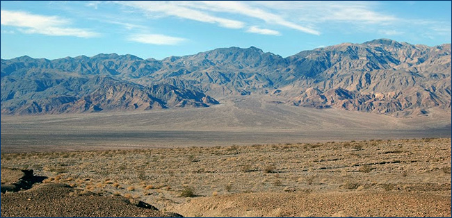
An alluvial fan forms in Death Valley as sediment washes down from the mountains beyond. Photo by Dave Smith.
Moraga Formation
Beginning around 9.5 million years ago, a period of volcanic activity began with a series of basaltic lava flows and the occasional tuff that buried the Orinda Formation. Clearly there was no break in deposition between the uppermost layer of the Orinda and the lowermost lava flow of the Moraga because that lowermost flow has clearly "baked" the uppermost rocks of the Orinda. The lava flows and igneous intrusions associated with it originated from Round Top, located a little over a mile southeast of the tunnel. As noted earlier, these intrusions had been encountered during construction of the previous three bores but the frequency with which they occur has diminished with each successive bore, probably because each new bore has been farther away from Round Top. The igneous dikes of the first two bores were some of the worst rocks encountered, as they were weak and soft when wet.
Dealing with the geology: Excavation and support
The Geotechnical Baseline Report evaluated rock units based on rock mass structure (ranging from disintegrated to massive), surface conditions along discontinuities (very poor to very good), degree of fracturing (very intensely to slightly), strength of intact rock (friable, i.e., easily crumbled, and weak to very strong), hardness of intact rock (soft to hard), and degree of weathering (severely weathered to fresh). These rock types were then grouped into ground classes (see the graphic below) based on their expected behaviors within the tunnel. The behaviors considered included block failure, slaking, softening, swelling, raveling, and shallow shear failure.

Click on the image to see an enlargement. The classifications are based on cores taken from borings. Rocks ranked 4 are the weakest and those ranked 1, the strongest. Based on Figure 2, Summary of Geologic Data for Tunnel Alignment, Caldecott Improvement Project, State of California Department of Transportation, Dec 2007.
From the graphic we can see that the Orinda Formation was expected to have the strongest rocks, with the Claremont Formation a close second. But still, because of the fractured, unstable nature of the East Bay Hill's rocks, the GBR specified that the Sequential Excavation Method (SEM) — also known as the New Austrian Tunneling Method (NATM), a system developed in Europe in the early 1960s — be employed. Instead of utilizing stiff supports to bear the ceiling load, the SEM uses the inherent strength of the surrounding rock as part of the support system, thereby keeping materials and costs to a minimum. The tunnel design and specifications outlined in the Fourth Bore's GBR were all based on the SEM philosophy.
The SEM is a very flexible approach to tunneling. Based on rock strength and behaviors, practically all aspects of the process can be modified for the conditions, whether it be round length (distance of each new advance in the excavation), the type of support to be installed and the timing of its installation, the need for additional support, or the subdivision of the excavation into multiple stages of excavation in which the tunnel is gradually enlarged.
The GBR specified that the tunnel be excavated in two stages: first, the top heading, followed by the bench and invert. This two-stage process is done to maintain tunnel stability and to control ground movement.
The GBR is the contractor's blueprint for the tunnel, providing information on where a specific kind of rock will be encountered, its condition and possible behavior, and what kind of support is appropriate. However, an accurate assessment can only be made during actual excavation. So after each advance or round — generally 8 to 12 feet — supports are tailored to the rock conditions.
In general, the steps taken after each round of excavation of the top heading, are as follows:
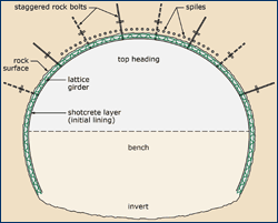
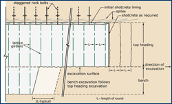
Click on either image to see an enlargement. A cross-section (top) longitudinal section (bottom) of tunnel with the initial supports in place. Adapted from graphics on the U.S. Department of Transportation-Federal Highway Administration's online Technical Manual for Design and Construction of Road Tunnels. This is an excellent source of information on all aspects of SEM and other tunneling methods.
- A layer of fiber-reinforced concrete, called shotcrete, is sprayed over the newly exposed rock surface, including the face if it requires stablizing. The shotcrete may be applied during excavation if the face or crown (roof) shows signs of failure.
- The lattice girder is installed. Lattice girders are typically constructed of three parallel steel bars arranged in a V-configuration and connected by welded diagonal elements. These can be manufactured to fit the geometry of any tunnel. The girders are muscled into place and bolted to the wall.
- Rock bolts are installed in the previously excavated round by a large, specially designed rockbolting machine that drills the holes, installs the bolts, and grouts them in place.
- A second layer of shotcrete is applied over the rock bolts.
- A third and final layer of shotcrete is applied on top of the second layer two rounds back, after that second layer has had time to set.
- To help stabilize the ceiling during excavation of the next round, spiles — long metal rods or pipe — are driven into the ground at a low angle just above the crown. The near end of the spiles receive support from the last installed shotcrete and lattice girder; the far end is beyond the length of the next round so it is supported by the native rock. Holes for the spiles are drilled by a machine called a drill jumbo.
- Probe holes are drilled into the excavated face so that ground conditions can be assessed prior to excavating the next round. Drain holes may also be drilled into the face to allow ground water to drain from the rock ahead. When necessary, fiberglass or resin face dowels are used to improve the stability of the excavated face. The roadheader can easily cut through the dowels when excavation resumes.
- Excavation of the top heading resumes, with the roadheader (westbound) and modified Caterpillar excavator (eastbound), cutting into the rock face. And then it's back to step 1.
The Fourth Bore was excavated from both the Orinda and Oakland sides, with the excavation on the westbound side getting underway in August of 2010. About three quarters of the tunnel was excavated from the Orinda side because the Orinda and Claremont formations were more stable than the Sobrante. The eastbound, Oakland side excavation began in March of 2011. The breakthrough of the top heading excavations took place on November 29, 2011, about 200 meters in from the Oakland side.
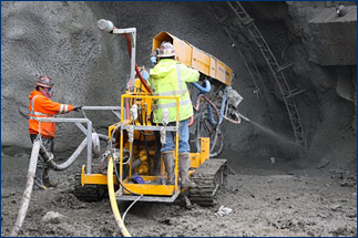
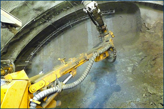
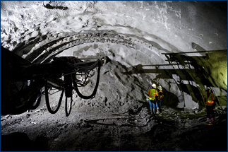
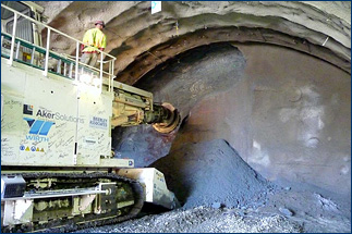
Top left: Shotcrete is sprayed over a lattice girder at the West Portal. Top right: Shotcrete is applied to the tunnel face to stabilize it. Note the ends of the spiles emerging from the crown's shotcrete. Bottom left: A probe hole is drilled into the face prior to the next round of excavation to see what kind of rocks lie ahead. Bottom right: The roadheader at work excavating the top heading. These and all Fourth Bore photos that follow are by Caltrans photographers Bill Hall or John Huseby; some may be by Karl Nielsen of the Metropolitan Transportation Commission.
By the time of the breakthrough, all of the top heading and most of the bench had been excavated in the relatively short stretch of tunnel that had begun on the Oakland side. At this point, the roadheader reversed direction and was used to remove the bench in the long stretch back to the Orinda portal. A smaller roadheader was used to excavate seven cross-passages — essentially emergency exits — connecting the Fourth Bore to the Third Bore.
With the digging portion of the project about done, the next step was to install a waterproof membrane on the initial shotcrete coating. Gantries were constructed outside the west portal; these mobile rigs moved westward through the tunnel on rails, enabling crews to install both the membrane and the final, two-foot-thick concrete coating poured over a network of reinforcing bar. Where the rock at the base of the tunnel (the invert) was competent and not prone to swelling or expansion, it was not necessary to pour a concrete floor (see graphic below), but where the rock was questionable, a concrete invert slab was installed. The first 50 meters of the Sobrante Formation and about 300 meters at the eastern end in the Orinda Formation received the invert slab treatment.
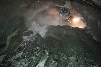
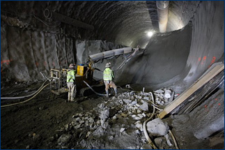
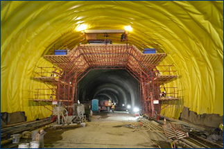
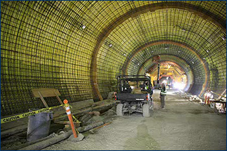
Top left: The roadheader breaks through the rock separating the westbound and eastbound excavations. Top right: Removing the bench. Bottom left: Workers on the gantry apply the waterproofing membrane to the tunnel walls. Bottom right: Following the application of the waterproofing membrane, a network of rebar is installed for the final layer of poured-in-place concrete.
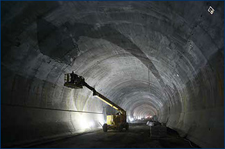
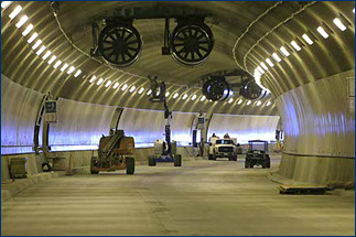
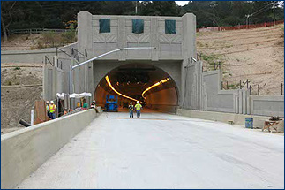
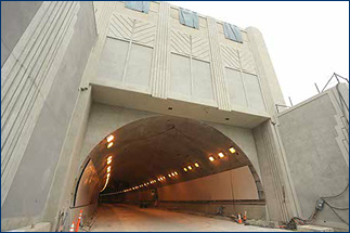
Top left: The final coating of concrete has been poured. Top right: Jet fans are installed in the ceiling to control tunnel ventilation. Bottom left: A view of the east (Orinda side) portal. Bottom right: The west (Oakland side) portal.
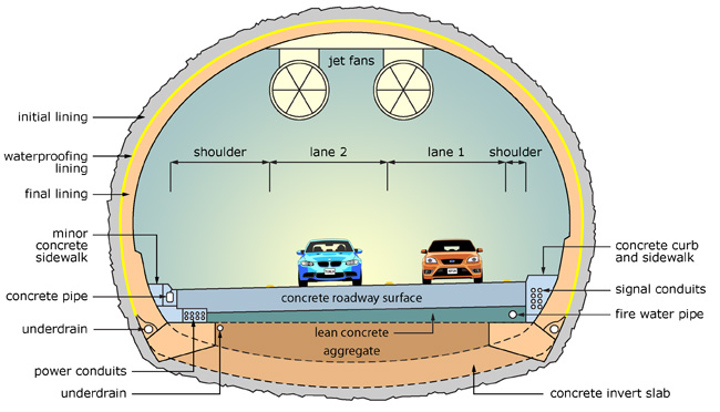
A cross-sectional view of the completed Fourth Bore. The concrete invert slab is indicated by dashed lines since the slab was not needed for the entire length of the tunnel. Based on a graphic provided by Chris Risden, Senior Engineering Geologist, Caltrans' Office of Geotechnical Design West.
The SEM proved to be the perfect excavation approach for the Fourth Bore. The contractor for the project, Tutor-Saliba Corporation of Sylmar, California, (cue the trumpets!) completed the job with an excellent safety record and no cave-ins.
However, even with the final tunnel coating installed, there were still many months of work remaining that involved installation of operations, communications, ventilation, and emergency systems. More can be learned about this stage on the Fourth Bore website. Just under four years since the groundbreaking ceremony (January 2010), the Fourth Bore was opened to traffic on November 16, 2013.
Next, we turn our attention to the fossils recovered during tunnel construction.
1 Page 69, Caldecott Improvement Project: Geotechnical Baseline Report, prepared by Jacobs Associates, June 2009. 100 pp.
2 Page 6, Field Trip Guide "Tunneling Through a Miocene Plate Boundary" by Chris Risden and Ivy Morrison. Courtesy of Chris Risden, Senior Engineering Geologist, Caltrans' Office of Geotechnical Design West.
3 Page 5, Caldecott Improvement Project: Geotechnical Baseline Report.
4 Page 40, Sloan, D. 2005. Geology of the San Francisco Bay Region. University of California Press. 335 pp.
5 Page, B.M. 1950. Geology of the Broadway Tunnel, Berkeley Hills, California. Economic Geology 45(2):142-166. DOI: 10.2113/gsecongeo.45.2.142
Geologist Benjamin Markham Page (1911-1997) received three academic degrees from Stanford University and then taught there for 33 years, retiring in 1976. In the 1960s, Page was one of the first to see that plate tectonics helped to explain California geology. He continued to conduct research, publish and teach until his death.
6 Quoted excerpts are from Caldecott Improvement Project: Geotechnical Baseline Report. Prepared by Jacobs Associates. June 2009. 100 pp.
Next page >>